Rule No. 1: Stock values always come first.
Change one thing at a time, listen or measure the result, and keep a record of what you changed. A modification is not automatically an improvement. Keep the original parts so the board can always be returned to the reference circuit.
REFERENCE CIRCUIT
Know the starting point
These are the present standard component values. Modifications below refer back to this table.
| Reference | Stock value | Normal function |
|---|
| U1 | NE5534 | Single audio operational amplifier |
| R1 | 100 kΩ | Bias network |
| R2 | 100 kΩ | Bias network |
| R3 | 120 kΩ | Input network |
| C1 | 1 µF | Input coupling |
| C2 | 0.1 µF | Bias / decoupling network |
| C3 | 1 µF | Output coupling |
| C4 | 0.1 µF | Bias / decoupling network |
| C5 | 22 pF | NE5534 external frequency compensation, between COMP and COMP/BAL (pins 5 and 8) |
| Control | 500 kΩ | Off-board gain / feedback control |
| Supply | 9 V | Standard battery operation |
1 — OP-AMP SWAPPING
The active device
The stock NE5534 is part of the character of the original circuit. Other single 8-pin op-amps can be interesting, but an 8-pin package alone does not make a part electrically compatible.
| Device | 9 V μ-Amp suitability | What to expect / watch |
|---|
|
NE5534
Datasheet
|
STOCK |
Reference device. Use this when comparing any other experiment. |
|
NE5534A
Datasheet
|
Direct-family option |
The A-grade version of the NE5534. It is from the same 5534 family and adds a guaranteed maximum equivalent-input-noise specification. Think of it as a tighter noise grade rather than a completely different-sounding circuit. |
|
SE5534
Datasheet
|
Direct-family option |
Military-temperature version of the 5534 family. Historical specifications characterize the SE device over approximately −55°C to +125°C, compared with the commercial-temperature NE version. |
|
SE5534A
Datasheet
|
Direct-family option |
Combines the wider military temperature range of the SE5534 with the A-grade noise specification. Vintage ceramic versions are especially interesting to collectors and period-style builds. |
|
TL071
Datasheet
|
Reasonable experiment |
Single FET-input device with the normal 2/3/4/6/7 op-amp pin positions. Its input behavior and noise characteristics differ from the NE5534, so compare by ear and on the bench. |
|
OPA134
Datasheet
|
Promising experiment |
Single FET-input audio op-amp rated for supplies well below 9 V. Pins 1, 5 and 8 are not used internally, which makes its auxiliary-pin arrangement simpler than the NE5534. |
|
OPA604
Datasheet
|
Borderline at 9 V |
Its specified minimum total supply is 9 V, so a fresh battery is already at the lower limit. A battery that has fallen below nominal voltage leaves no rating margin. |
|
LM741
Datasheet
|
Not recommended |
The commonly specified minimum total supply is 10 V. That makes it a poor choice for the standard single-9-V μ-Amp even though its familiar DIP pinout looks tempting. |
Identifying ceramic 8-pin 5534 packages
Some older 5534-family parts were supplied in hermetically sealed ceramic dual-inline packages. These use the same basic 8-pin through-hole footprint as the normal DIP version, so a ceramic DIP can physically fit the μ-Amp U1 position or an 8-pin DIP socket. Always confirm the actual manufacturer datasheet and pinout before installing an unfamiliar vintage part.
Suffixes you may encounter
- Texas Instruments JG: historical TI documentation lists SE5534JG and SE5534AJG as 8-pin ceramic DIP versions.
- Signetics / Philips: vintage listings include ceramic parts such as SE5534AF, SE5534FE and SE5534AFE. Because suffix usage changed between manufacturers and eras, verify the package from the original datasheet or device marking rather than relying on the last letters alone.
- /883 or /883B markings: these may appear on military-screened ceramic parts and are another clue that the device came from a high-reliability product line.
Why builders seek ceramic CERDIP parts
- Hermetic construction. Ceramic packages can be glass- or metal-sealed to protect the die and bond wires from moisture and contamination over long service periods.
- Harsh-environment heritage. Many SE-grade ceramic parts were intended for military or industrial temperature ranges and high-reliability service.
- Vintage appearance. Grey, white or gold-accented ceramic packages give a custom μ-Amp a distinctive period or military-surplus look.
Do not assume ceramic means better sound. Package material, screening grade and electrical grade are separate issues. Treat a ceramic 5534 primarily as a historically interesting and potentially higher-reliability version, then compare its actual electrical and audible performance against the stock device.
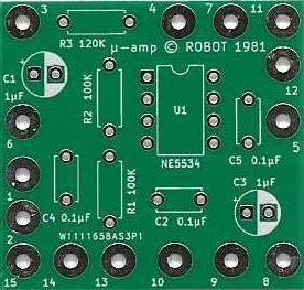
Important about C5: C5 is the small 22 pF NE5534 frequency-compensation capacitor, connected between COMP and COMP/BAL — pins 5 and 8. The component-side board photo above carries an older / incorrect silkscreen marking of 0.1 µF at C5. Do not use that printed value as the parts specification. We will also compare this with the surviving original μ-Amp hardware as the historical build is documented.
A socket makes this much easier
For a board intended for experimenting, fit a good-quality 8-pin DIP socket and plug U1 into the socket rather than soldering the IC directly to the PCB. This makes comparisons easy and protects the board from repeated desoldering.
Remember that the socket adds height. Check the guitar cavity before committing to it, and always verify pin 1 orientation before powering the board.
Optional offset trimming
The 5534 family also provides balance / offset-adjustment facilities on its auxiliary pins. These are separate from the normal audio inputs and output, and are distinct from the 22 pF frequency-compensation function.
For a normal AC-coupled μ-Amp installation, DC offset trimming is generally unnecessary. A precision-minded builder may experiment with an offset-null network, but it should be treated as an advanced modification and wired from the exact manufacturer data sheet for the device being used.
Do not casually combine an offset-null network with C5 changes. Pins 5 and 8 are also involved in the NE5534 compensation arrangement, so any auxiliary-pin modification should be considered together with the compensation requirement.
2 — CAPACITOR TUNING
Frequency response, bias and character
Capacitor changes can range from gentle frequency shaping to major changes in operating behavior. C1 and C3 are the easiest places to experiment; the bias / decoupling capacitors and the NE5534 compensation capacitor deserve more caution.
C1 — input coupling
Stock: 1 µF. Reducing C1 raises the low-frequency corner and can progressively thin the bottom end before the signal enters the amplifier stage.
Useful comparison values
- 0.47 µF — mild change
- 0.1 µF — more obvious bass reduction
- 0.047 µF — stronger shaping
- 0.01 µF — deliberately bright / thin experiment
Because the 500 kΩ control participates in the feedback network, do not assume a single fixed cutoff frequency from C1 alone.
C3 — output coupling
Stock: 1 µF. C3 blocks the circuit’s DC bias from the switched output. Smaller values can roll off bass depending on the input impedance of whatever follows the guitar.
A change here may behave differently into a 1 MΩ amplifier input than it does into a much lower-impedance pedal or device, so test the actual rig.
C2 and C4 — bias / decoupling
Stock: 0.1 µF each. These are part of the bias and decoupling arrangement rather than simple tone capacitors.
The 0.1 µF value is also a common local supply-bypass value in NE5534 applications. That is one reason it must not be confused with C5: 0.1 µF decoupling and 22 pF compensation are completely different jobs.
They can be experimented with, but treat the pair as circuit-stability and bias components. If a change causes slow start-up, thumps, oscillation, hiss or unstable DC conditions, return to stock before changing anything else.
C5 — NE5534 compensation
Reference value: 22 pF. C5 connects the NE5534 COMP and COMP/BAL pins (pins 5 and 8) and affects high-frequency compensation / stability rather than acting as an audio coupling or tone capacitor.
Texas Instruments characterizes the 5534 with values such as 22 pF and, for some loading conditions, 47 pF. Changing C5 can alter slew rate, bandwidth and stability, so this is not a casual “tone capacitor” substitution.
If experimenting
- Begin with the 22 pF reference value.
- Change only C5 and check the output with an oscilloscope if possible.
- Watch for ultrasonic oscillation, ringing or unexpected noise even if the guitar sounds normal.
- If a different op-amp is installed, follow that device’s data sheet rather than assuming it wants the same compensation capacitor.
3 — RESISTOR EXPERIMENTS
Loading, bias impedance and noise
R3 — 120 kΩ input network
R3 is in the signal path ahead of the unusual 500 kΩ gain / feedback control. Changing it affects the relationship between the pickup, the control and the amplifier stage.
Larger values generally reduce loading from this part of the network; smaller values increase it. But R3 should not be described as the circuit’s entire input impedance by itself.
For controlled experiments, try modest steps around the stock 120 kΩ value rather than jumping immediately by a factor of ten.
R1 and R2 — keep them matched
Stock: 100 kΩ / 100 kΩ. These two resistors establish the mid-supply reference used by the single-battery circuit.
- Lower matched values create a stiffer reference but consume more battery current.
- Higher matched values reduce divider current but increase impedance and can make the bias node more sensitive to leakage and noise.
- Changing both to 1 MΩ is therefore not automatically an “input impedance upgrade.”
If you alter them, change both together and keep their values closely matched.
Resistor type: 1% metal-film resistors are a sensible low-noise choice for experimental builds. Carbon-film or older carbon-composition parts can also be tried for historical interest, but any difference should be evaluated rather than assumed.
4 — THE 500 kΩ CONTROL
More than a volume knob
The μ-Amp control is unusual: the incoming signal is applied to the pot wiper while the pot also participates in the op-amp feedback path. Changing the pot changes more than simple output volume.
Taper experiments
A 500 kΩ audio-taper and a 500 kΩ linear-taper pot can both be interesting because they distribute the electrical change differently across the knob rotation.
Rather than declaring one “correct” for every player, compare them for control feel. The important reference is the stock 500 kΩ resistance range.
Resistance experiments
Trying another total resistance changes the feedback range and the impedance seen around the summing node.
- 250 kΩ — useful lower-range experiment.
- 500 kΩ — stock reference.
- 1 MΩ — useful higher-range experiment.
Expect the maximum boost and control behavior to move. Recheck clipping and stability rather than treating the value as a simple volume-pot substitution.
5 — POWER SUPPLY
Keep 9 V as the reference
The standard μ-Amp is a 9 V product
Use a single 9 V battery as the baseline for all comparisons. Higher-voltage experiments should not be treated as a casual battery substitution.
Before applying any higher supply, verify the voltage ratings and polarity of every capacitor, the chosen op-amp supply rating, the battery-switching arrangement and the rest of the installed wiring. If those details have not been checked, stay with 9 V.
6 — GOOD MODDING PRACTICE
Make experiments reversible
Before changing anything
- Photograph the board and wiring.
- Write down the stock value and orientation.
- Disconnect the battery.
- Change only one variable at a time.
- Keep the original component in a labeled bag.
- Test the board before reinstalling it in the guitar cavity.
What to compare
- Noise and hum
- Control range and taper
- Bass and treble balance
- Maximum clean boost
- Compression / clipping behavior
- Battery current and battery life
- Oscillation or instability
EXPERIMENT LOG
Write down what actually happened
A simple log is more useful than relying on memory after several component swaps.
| Part changed | New value / part | Result / listening notes |
|---|
| | | |
| | | |
| | | |
| | | |
| | | |
Datasheets win: Before substituting any IC or polarized component, check the manufacturer’s current datasheet for pinout, supply limits and orientation. Two parts that physically fit the same socket are not necessarily electrical substitutes.