INSTALLATION & WIRING
μ-Amp Installation Guide
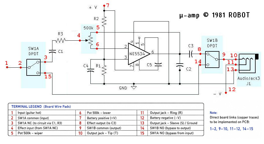
Wiring reference for the preassembled onboard guitar preamplifier, including the numbered PCB pads, recommended wire colors, 500 kΩ control, DPDT bypass switch, stereo output jack and 9 V battery.
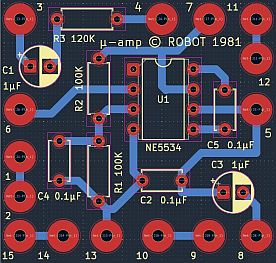
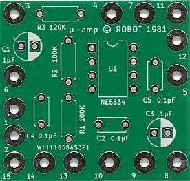
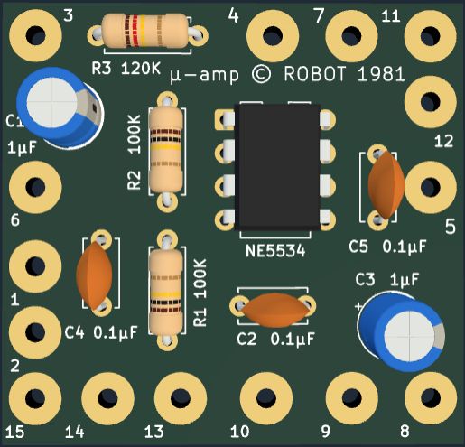
PAD LEGEND
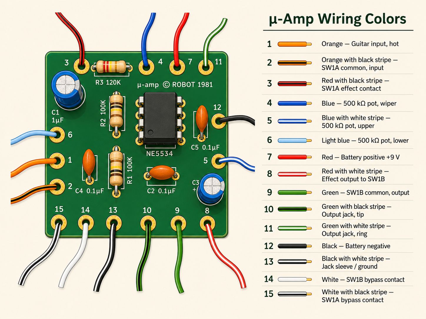
Numbered connections and wire colors
The recommended colors make the off-board wiring easier to identify during installation and later service.
| Pad | Wire color | Connection |
|---|---|---|
| 1 | Orange | Guitar input — hot |
| 2 | Orange / black stripe | SW1A common — input |
| 3 | Red / black stripe | SW1A effect contact |
| 4 | Blue | 500 kΩ pot — wiper |
| 5 | Blue / white stripe | 500 kΩ pot — upper |
| 6 | Light blue | 500 kΩ pot — lower |
| 7 | Red | Battery positive +9 V |
| 8 | Red / white stripe | Effect output to SW1B |
| 9 | Green | SW1B common — output |
| 10 | Green / black stripe | Output jack — Tip |
| 11 | Green / white stripe | Output jack — Ring |
| 12 | Black | Battery negative |
| 13 | Black / white stripe | Jack Sleeve / ground |
| 14 | White | SW1B bypass contact |
| 15 | White / black stripe | SW1A bypass contact |
BEFORE YOU START WIRING
Open the guitar and plan the installation first
For these instructions, we will assume you have the version of the μ-Amp with the color-coded wires already soldered to the PCB.
Decide where the parts will go before cutting or moving any wires
Open the guitar's control cavity or rear access panel and look at the space available. Decide where the μ-Amp board, control, switch and 9 V battery can be mounted before disconnecting anything.
This first look will help you decide where the PCB can be mounted safely, which existing controls can remain, whether a new control or switch must be added, which supplied wires should be used, and whether any wires should be shortened or replaced with longer ones.
Plan the battery location now as well. Decide whether the guitar will use a simple 9 V snap clip, a mounted battery holder, a battery drawer, or another suitable arrangement. Battery location affects the available cavity space, wire length and routing, and how easily the battery can be replaced later.
There is no single required mechanical layout. Different guitars provide different amounts of space and different existing controls, so the cleanest installation may vary from one instrument to another.
CONTROL OPTIONS
Several arrangements are possible
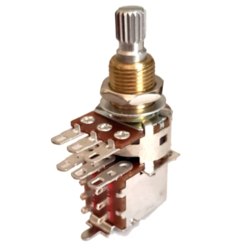
SKU: CPPB500S
The μ-Amp needs one 500 kΩ control and one DPDT effect / bypass switch, but those functions do not have to be installed as two completely separate new parts.
These are installation arrangements, not a requirement for the customer to hunt down miscellaneous parts. The appropriate μ-Amp control and switching hardware can be supplied for the chosen installation.
- Add a new 500 kΩ pot and a separate DPDT switch.
- Reuse an existing control location. In some guitars an existing tone-control position may be repurposed for the μ-Amp control.
- Use a 500 kΩ push-pull pot with an integrated DPDT switch. This combines the control and bypass switch in one existing control-hole location.
- Use a stacked or dual control if another guitar function must be retained. Only one 500 kΩ track is required by the μ-Amp itself.
GUITAR-SPECIFIC EXAMPLE
Gibson-style guitar — four existing control holes
For a conventional two-humbucker Gibson-style guitar with two volume controls and two tone controls, the μ-Amp can be installed without drilling additional control holes. This is a particularly clean arrangement because all four original control positions remain in use.
The guitar's pickup-selector switch remains in service. Instead of each humbucker having its own separate volume and tone controls, the selected pickup or pickup combination feeds a shared pickup volume and a shared master tone. The two freed control positions provide a full-size μ-Amp master control and an easy-to-reach dedicated bypass switch.
What changes: the guitar no longer has independent neck and bridge volume settings or independent tone settings. In the middle pickup-selector position, both pickups are controlled together by the shared volume and master tone.
Why this arrangement works well: it preserves the original four-hole appearance, requires no additional hole in the guitar top, and keeps the μ-Amp control and bypass switch immediately accessible to the player.
The PCB links are choices made one connection at a time
The μ-Amp does not require one complete wiring method for the entire installation. Several pad pairs are already joined by copper traces on the PCB. At each such connection, you may use the board trace or make the same connection directly between the off-board parts.
An installation can therefore use a mixture of both approaches. As we proceed step by step, the available choice will be pointed out where it occurs.
STEP 1
Locate the guitar's existing output wire
Find the wire that presently carries the guitar signal to the output jack
Before disconnecting anything, identify the guitar's existing hot output wire. In many guitars this runs from the output of the volume control to the Tip terminal of the existing output jack.
Follow that wire visually and note where both ends are connected. This is the signal path that the μ-Amp and its bypass switch will be inserted into.
Do not cut or remove the wire yet. First decide whether it is long enough and conveniently routed to be reused. Its location, together with the planned locations of the board and switch, will help determine the cleanest way to continue.
STEP 2
Replace and reroute the output jack
A stereo output jack is required
The μ-Amp uses the guitar's output jack to switch the battery off when the guitar cable is unplugged. The output jack must therefore be a stereo (Tip / Ring / Sleeve) jack.
If the guitar presently has a mono jack, replace it with a stereo jack.
- Tip carries the guitar's final audio output.
- Ring switches the battery negative connection.
- Sleeve remains the instrument ground.
Do not permanently connect Ring to Sleeve. Keeping them separate is what allows removing the guitar plug to disconnect the battery.
Now decide how to reroute the original output signal
The guitar's original hot output can no longer remain connected directly to the jack Tip, because the μ-Amp and bypass switch must be inserted into that signal path.
- Reuse the existing output wire and route it directly to SW1A common.
- Route the existing output wire to the μ-Amp board. Connect it to the Pad 1 wire; the built-in 1 ↔ 2 copper trace then carries the signal to the Pad 2 wire, which can go to SW1A common.
- Replace the existing output wire with the supplied μ-Amp wire. The replacement may likewise go through the Pad 1 ↔ 2 board connection or directly to SW1A common.
The important point is that the guitar's original output signal now goes to the input side of the μ-Amp / bypass switch, not directly to the jack Tip. The jack Tip will be connected to the switched output side later.
STEP 3
Wire the DPDT effect / bypass switch
First identify the two switch poles
The switch may be a separate DPDT toggle or the DPDT section of a 500 kΩ push-pull control. Electrically, the connections are the same.
Before soldering, use a continuity meter to identify the common terminal for each pole and determine which throw connects to that common in each switch position. Do not rely only on the physical position of the lugs, especially on a push-pull control.
Once the two poles are identified, wire them as follows:
- SW1A common: Pad 2 — orange / black stripe
- SW1A effect throw: Pad 3 — red / black stripe
- SW1A bypass throw: Pad 15 — white / black stripe
- SW1B common: Pad 9 — green
- SW1B effect throw: Pad 8 — red / white stripe
- SW1B bypass throw: Pad 14 — white
The bypass connection gives you another choice
Pads 14 ↔ 15 are already connected together by a copper trace on the μ-Amp board. If you connect the Pad 14 and Pad 15 wires to their respective bypass switch lugs, the board completes the bypass path for you.
Or, if it makes the installation cleaner, connect the two bypass switch lugs directly to each other instead. In that case, the Pad 14 and Pad 15 wires are not needed for that connection. Insulate any unused wire ends so they cannot touch another terminal or ground.
When finished, one switch position should connect 2 → 3 and 9 → 8 for the μ-Amp path. The other should connect 2 → 15 and 9 → 14 for bypass.
STEP 4
Wire the 500 kΩ μ-Amp control
Use one 500 kΩ potentiometer track
The μ-Amp requires one 500 kΩ potentiometer. This can be a new standalone control, a suitable existing control that you choose to repurpose, or one track of a push-pull / stacked control.
If an existing tone-control position is being repurposed, make sure the control is actually 500 kΩ and disconnect it from its former tone circuit before wiring it to the μ-Amp. If you want to keep the original tone function in the same location, use an appropriate dual or stacked control instead of sharing one resistive track between the two circuits.
Wire the three μ-Amp control connections exactly as follows:
- Pad 4 — blue — pot wiper
- Pad 5 — blue / white stripe — pot upper terminal
- Pad 6 — light blue — pot lower terminal
The center lug of a conventional pot is normally the wiper, but verify the terminal arrangement of the particular control you are using.
If you are using a push-pull control, remember that the potentiometer and the DPDT switch are electrically separate parts sharing one mechanical assembly. Wire the pot section here exactly as above; the switch section is wired separately as described in Step 3.
Leave enough slack for the control to be removed for service, but avoid leaving unnecessary loops of wire in the cavity.
STEP 5
Finish wiring the stereo output jack
Connect Tip, Ring and Sleeve
At this point the guitar's original output signal has been rerouted through the μ-Amp / bypass switch. The stereo output jack can now be connected to the switched output, battery negative and ground.
Tip — final audio output
The jack Tip must connect to SW1B common. You have two choices:
- Use the PCB link. Connect the green Pad 9 wire to SW1B common and the green / black Pad 10 wire to the jack Tip. Pads 9 ↔ 10 are already joined by a copper trace on the PCB.
- Wire it directly. Connect SW1B common directly to the jack Tip. In that case the Pad 10 wire is not needed for this connection. Insulate any unused wire end.
Ring — battery negative switch
The jack Ring is used only to switch the battery negative connection when a guitar plug is inserted. Again, you have two choices:
- Use the PCB link. Connect the green / white Pad 11 wire to the jack Ring. The battery negative lead will connect to Pad 12 in Step 6. Pads 11 ↔ 12 are already joined on the PCB.
- Wire it directly. Connect the battery negative lead directly to the jack Ring. Pads 11 and 12 are then not needed for that connection.
Sleeve — instrument ground
Connect the black / white Pad 13 wire to the jack Sleeve. Reconnect the guitar's existing ground wire to the Sleeve as well.
Grounding and shielding
The μ-Amp, the guitar controls and any cavity shielding should share a common instrument ground. Pad 13 connects the μ-Amp ground to the Sleeve of the output jack. The guitar's existing ground connection should also remain connected to the Sleeve.
It is common practice to run a bare or insulated ground wire between the metal cases of the volume and tone controls and solder it to each pot case. Keep this ground path simple. Do not form a closed loop of ground wire, since a loop can act as an antenna and increase hum or other electrical noise.
Many guitars also benefit from lining the control cavity and the underside of its cover with adhesive copper shielding foil. The pieces of foil should make electrical contact with one another and the shielding should be connected to the instrument ground at one deliberate point.
Keep the μ-Amp PCB itself insulated from the copper foil, conductive shielding paint, pot cases and other metal parts so the underside of the board cannot short against the shielding.
Important: Do not connect the jack Ring permanently to Sleeve. The battery is switched off only because the Ring remains separate until a plug is inserted.
STEP 6
Connect the 9 V battery
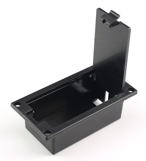
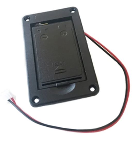
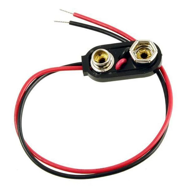
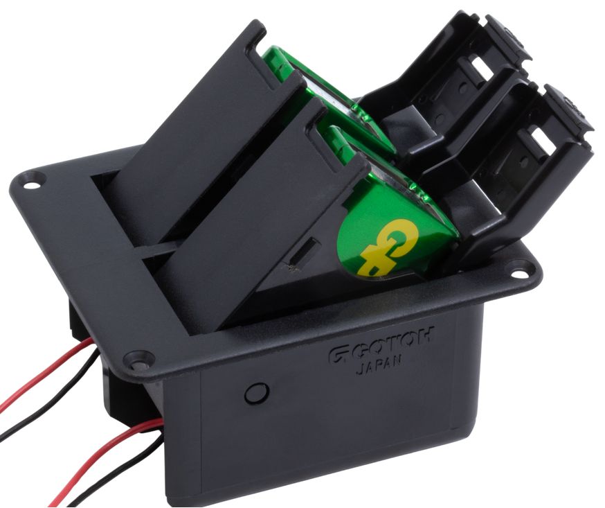
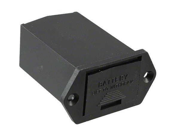
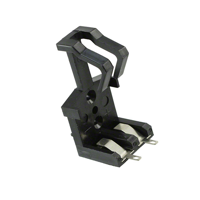
Examples of 9 V battery clips, holders and service-access arrangements. Choose a style that fits the available guitar cavity and provides reasonable access for battery replacement.
Several battery-connection arrangements are possible
The standard μ-Amp operates from a single 9 V battery. The board may be supplied in several ways depending on how much of the battery installation the builder wants to complete.
- Prewired 9 V battery clip. A conventional snap clip may be supplied already connected to the μ-Amp battery leads.
- Battery wires supplied but not connected to a clip. This lets the installer cut the leads to the required length and attach a preferred clip or holder.
- No battery wires. The installer may provide the complete battery wiring and holder arrangement.
A simple loose snap clip is usually the easiest arrangement, but a mounted holder or battery drawer can make future battery replacement much easier. The photographs at right show several possible styles.
Make the electrical connections
Do not snap a battery onto the clip yet. Complete the wiring first, inspect it, and connect the battery only when the installation is ready for its first test.
- Battery positive (+): connect the battery supply's red lead to the red Pad 7 wire.
- Battery negative (−): connect the battery supply's black lead either to the black Pad 12 wire, using the built-in 12 ↔ 11 PCB link to the jack Ring, or directly to the jack Ring if you chose that method in Step 5.
The battery negative lead should not connect directly to ground. When the guitar cable is removed, the stereo jack must interrupt the battery-negative path so the μ-Amp does not continue drawing power.
About dual-battery holders
Dual 9 V holders are available and may be useful in other projects or special installations. Depending on how such a holder is wired, two batteries can be arranged in series or parallel. The standard μ-Amp installation uses one 9 V battery, so do not substitute an 18 V series arrangement unless a version of the circuit is specifically intended for that supply.
Once Steps 1 through 6 are complete, all electrical connections to the μ-Amp should be accounted for. The remaining work is to secure and insulate the board, inspect the wiring, and perform the first power-up test.
FIRST POWER-UP
Check the installation before connecting the battery
- Battery + red lead checked at Pad 7.
- Battery − black lead goes to Pad 12 or directly to jack Ring, according to the wiring choice made in Step 5.
- Pad 13 (black/white) goes to Sleeve / ground.
- Pot is wired: Pad 4 wiper (blue), Pad 5 upper (blue/white), Pad 6 lower (light blue).
- SW1A and SW1B common and throw contacts have been verified.
- No solder bridges or loose strands.
- Unused wire ends are insulated.
- PCB is insulated from metal and shielding.
- Set the amplifier volume low.
- Connect a fresh 9 V battery and plug in the guitar cable.
- Test bypass first, then switch to μ-Amp.
- Operate the 500 kΩ control through its range.
- Unplug the guitar cable and confirm that the stereo jack disconnects the battery.
- Gently move the wiring to check for intermittent joints before closing the cavity.
TROUBLESHOOTING
What to check first
| Symptom | Check first |
|---|---|
| No sound in either position | Jack Tip/Sleeve, guitar hot, SW1A/SW1B commons, ground. |
| Bypass works; μ-Amp does not | Pads 3 and 8; Pads 4/5/6; +9 V on Pad 7; effect switch contacts. |
| μ-Amp works; bypass does not | Bypass connection between SW1A and SW1B — Pads 15/14 or direct wire. |
| Battery drains unplugged | Jack Ring/Sleeve wiring. Ring must not remain permanently grounded. |
| Hum / intermittent noise | Pad 13 ground, solder joints, long unshielded signal wires, PCB touching shielding. |
| No power with cable inserted | Stereo jack Ring contact and battery-negative wiring. |
PRINTABLE GUIDE
Keep the two-page installation guide on the bench.
The PDF contains the same wiring information in a compact printable format, including the board reference and wiring diagram.